Solving your starter motor woes
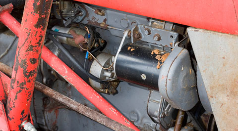
The opening part of this series laid out how the starter motor works, set the thing in the context of its electrical supply and suggested a few eyes-and-ears checks as the first steps in troubleshooting.
If the simple options didn’t nail down a problem, then it’s necessary to unleash a little technology. The Step-by-step section shows how to make certain that the battery is fully charged and able to deliver high current consistently.
Next, check out Voltage drop – what’s it about to get a grip on the principles, and finally work through the picture sequence to see what to put where. For best results, make the tests in the order shown.
Begin with the battery. For the six tests to make any sense, it is essential that the battery is fully charged and physically able to deliver the required high currents. If you are lucky enough to have a battery analyser, just let it do its stuff.
If not and if the battery cell caps can come off, use a hydrometer to establish the state of charge. Recharge as required for find a charged battery. Don’t jump-lead from another vehicle as the dodgy battery will still be in the circuit.
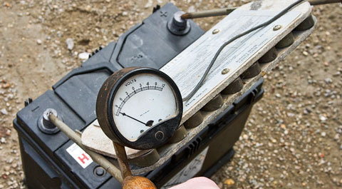
A battery can show a charge, yet still not deliver the current a starter needs, and a good analyser will quickly spot that. Or, if you have a load tester, connect it for 10 seconds (caution – spark/explosion risk) and watch battery voltage.
If this drops to around 9V and stabilises, the battery is serviceable. But if voltage falls like a stone, the battery has an internal problem and is scrap. After load-testing, a charged, healthy battery will quickly bounce back to at least 12.2V.
If you have no load tester and where cell caps can be removed, let the vehicle do the work. Switch on electrical loads, then have someone hold the keyswitch in start position. Wearing eye protection, peer into the cells. If one or more bubbles violently under load, the battery is on its way out and may be the problem; either way it’s no use for fault-finding.
A maximum of six checks, taking 15 minutes at most, should locate trouble. For each test a diagram shows where in the circuit to connect and a picture gives a typical example.
Before you begin, please note: It is essential that the battery is in good order for voltage drop test to be reliable.
During voltage drop tests, the engine should not fire, as you need to try to crank the starter for a few seconds – 10 at most. So disable the ignition or remove the fuel pump relay on petrol engines, pull the stop control or disconnect the fuel feed solenoid wire on older diesels.
Note: Later engines, particularly common-rail diesels, control fuelling electronically. Disabling these is harder, is usually machine-specific, and may involve pulling one or more fuses or relays.
Test 1: Find battery voltage under load
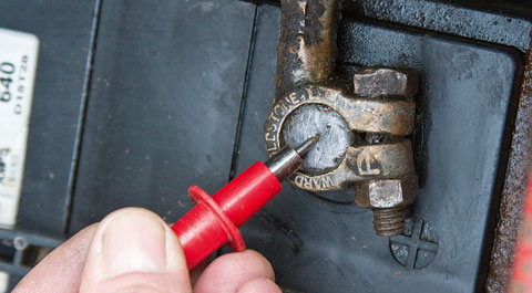
Connect a voltmeter between the battery posts (not the clamps!) and hold the keyswitch in the start position for 5-10 secs.
Jot down battery voltage as the starter tries to run. It should be 9V or higher in a 12V diesel system or 10V minimum for petrol engines.
Substantially below 9V when trying to crank suggests very heavy current drain, suggesting a major starter-motor fault. If voltage does not change and the starter won’t crank, go to Test 2.
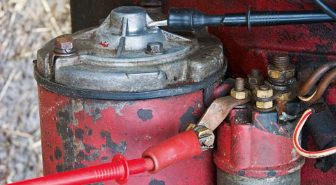
Test 2: Solenoid windings
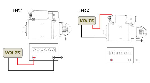
Check voltage at the solenoid input (feed) terminal while cranking – red meter lead to the terminal, black to the starter body or (preferably) the battery negative post. Voltage can be less than in test 1 but ideally within 0.5V of it.
If that’s true but the solenoid chatters or the engine is cranked unsteadily, the solenoid itself is duff. If voltage is zero or below 8V, then the keyswitch circuit wiring is broken or has poor connection(s).
Look to the fuse or fuse holder, the keyswitch itself, any safety interlock switches and the wiring. If all is well, go to Test 3.
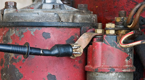
Test 3: Voltage at starter, under load
Put the voltmeter’s red probe on the starter’s input terminal (not on the solenoid) and the black one on the starter body. Now try cranking. If the motor turns and the voltage stays within 0.5V of the on-load battery value from test 1, the starter circuit is good.
If voltage is more the 0.5V below the battery value, there is high resistance in the supply line, the solenoid or the return path. Go to test four to six to find where it is. If the starter won’t crank, the motor or solenoid has died.
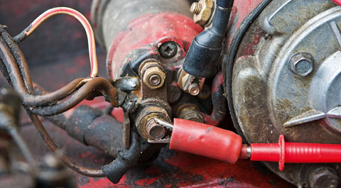
Test 4: Volt drop in supply line
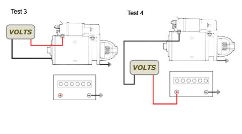
Here we’re looking for resistance in the path that current must take from the battery to the starter, including through the solenoid.
Put the voltmeter’s red probe on the battery positive (+) terminal and the black one on the starter motor’s input terminal. Before the start key is turned you should see resting battery voltage; in this case 12. Little or no voltage means the starter is faulty.
If on trying the starter, voltage drops to 250mV (0.25V) max, the supply side of the circuit is OK. A reading above 500mV (0.5V) shows high resistance in the supply side. To isolate it, check connections and the cable itself. If these are good, go to Test 5 to eliminate the solenoid from your enquiries.
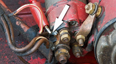
Test 5: Volt drop across solenoid contacts
Put the red voltmeter probe on the solenoid’s input post (the one that takes the heavy battery cable) and the black probe on the solenoid’s output post (the one which connects to the starter motor).
Before you try the starter, the meter should show resting battery voltage. On twisting the key, voltage should fall to 250mV (0.25V) max. If it does, the solenoid contacts are kosher and the unwanted resistance discovered in Test 4 must be in the supply cabling or joints.
But a high-voltage reading confirms that the problem is resistance in the solenoid’s internal contacts, so the starter needs fixing.
Test 6: Volt drop in the return (earth) line
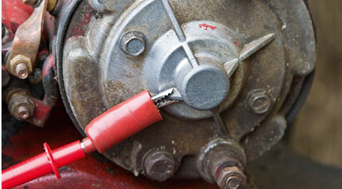
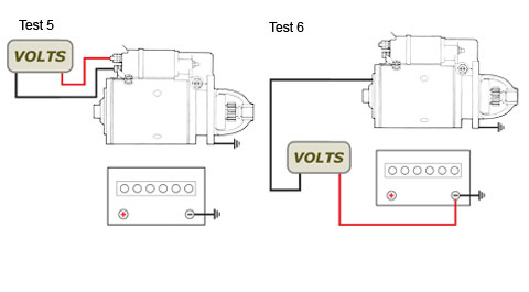
If Tests 4 and 5 found no problem on the supply side, then the path from the starter back to the battery holds the unwanted resistance. Put the red voltmeter lead on the starter’s end bracket and the black one on the battery’s negative (-) terminal.
On trying the starter, voltage should be under 0.25V. If over 0.5V, there is too much resistance in the current’s return path. Check all connections including the return lead/battery clamp joint, and the condition of any braided earth strap(s) between the starter, engine and frame.
Some starters attach a separate earth lead to a bolt which passes out from the end bracket; this can corrode internally to produce high resistance. The fix is simple – take the starter off, remove the end bracket, clean it and fit a new bolt.
Voltage-drop tests set out to find unwanted resistance in high-current circuits, typically starting and charging. Unlike bypassing suspect joints or components by probing with a live cable, volt-drop testing is safe and user-friendly.
Why not measure resistance directly? Any good meter with an ohms or continuity function can do that. The snag is that a sub-standard connection or cable may happily transmit the small test current sent out by a multimeter, but baulk at the heavy current demanded by a starter motor.
Volt-drop testing works by looking for voltage lost to high resistance. Electrical resistance works like your thumbs squeezing a hosepipe. If voltage is water pressure and current is its flow, downstream of the squeeze point the pressure (or voltage) will be lower, and water flow (or current) will be less. If the hose was supplying a water wheel, the wheel would slow down.
A poor connection adds resistance to the circuit, so the starter turns more slowly. The more the resistance, the slower it goes. And when resistance becomes total (as in a break in the current supply or return paths), the motor won’t turn at all.
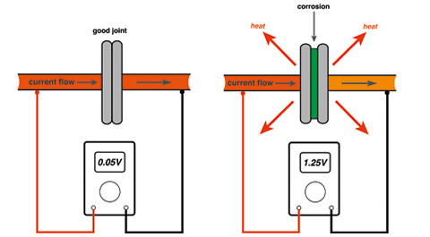
All cables and joints have some resistance, though it’s usually vanishingly small. So even in a properly sized cable carrying substantial current, a little voltage is always lost along its length (above left). As resistance grows the loss in voltage shoots up – and it’s that loss we’re looking for (above right).
What sort of volt drop is acceptable in a starting circuit? If the setup is healthy and uses thick enough cables, total drop should be no more than 0.5V while the starter is trying to crank. The bigger the voltage loss, the bigger the starter’s performance hit.
It’s handy to split the starting circuit into two halves. Everything up to the motor is the supply path, everything after it is the return or earth path. How and where do you measure voltage drop? Between any two points in the circuit. Just put one probe on a sensitive voltmeter at the beginning of the cable section or joint under test, and put the other probe anywhere after it in the circuit.
Now try operating the starter. The meter will show the voltage drop in the section between the probes, so you can see if it’s within limits. Small drops (say, 0.1V-0.2V) are normal, but the total drop should be under 0.5V. Generally, if resistance is big enough to substantially slow the starter, the voltage drop will be very noticeable. If there is no drop at all the circuit is broken; either a cable has failed or disconnected, or something is adrift in the starter.
Typical sources of unwanted resistance are corrosion between cable clamps and battery posts; corrosion between cable clamps and cables; frayed cables (which reduce current carrying capacity) and loose/corroded joints. Less obvious but equally debilitating are bad connections inside the starter