
Finding ways to deal with slurry
Installing a slurry separator has helped resolve slurry storage, handling and utilisation issues on one West Sussex dairy farm, Dairy Update reports
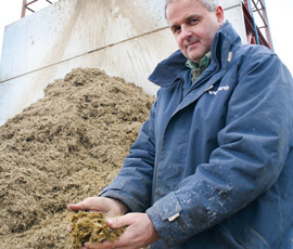
Slurry separation has proved a considerable step forward from the “nightmare of dealing with muck”, according to Neil Harrison of R Harrison and Sons.
Mr Harrson had seen the benefits of such a system on a neighbouring farm, so when he was faced with a shortfall in capacity to meet new NVZ rules, as well as a need to use nutrients more effectively, slurry separation provided the answer.
The family partnership operates three dairy units near Horsham, with a total of 1,100 mainly Jersey-Friesian crosses on 890ha (2,200 acres) of owned and rented land.
Initially a FAN screw separator was installed on the family’s 500-cow unit at Pallinghurst Farm – instantly relieving the marginal capacity of an old sleeper-walled lagoon. Following this success, a second separator was installed at the 400-cow operation at nearby Dedisham Farm, where a large area of open concrete adds to the volume of winter waste.
The problem
“The cows on this unit take self-feed silage from open-air clamps,” explains Mr Harrison. “The cubicle housing, feeding and loafing areas are scraped three times a day and with about half an acre of concrete in front of the cubicle sheds and 32-33in of rainfall, we’re collecting a lot of liquid.”
Before the separation project began, slurry and parlour washings were collected in a 2,500cu m earth-walled lagoon.
“We tried draining off liquid through a weeping wall to apply it by tanker, but it wasn’t very successful in the longer term,” Mr Harrison recalls.
Today, the scene is very different. Instead of a vast slurry lake, the concrete-floored lagoon now houses a 150cu m slurry reception tank and provides storage for the light, dry fibrous material extracted by the separator mounted high on a steel gantry alongside.
The liquid fraction is pumped to a new 20,000cu m reservoir. Its contents are applied to nearby land by dirty water irrigator and farther afield by a contractor’s vacuum tanker or umbilical application system.
“Solids are pushed away to storage and in two weeks turn black like compost; the smell goes completely,” reports Mr Harrison. “It stacks up nicely in a spreader, so we can put it on maize fields across the main road, or up to seven miles away where we have some very hungry ground. It puts some much-needed fibre and nutrients back on the land.”
Separator choice
Having dismissed roller screen separators because of concerns over running and long-term maintenance and repair costs, the screw press was selected.
The specific screw press separator chosen includes an oscillator that transmits pressure pulses into the inlet chamber to assist separation of sticky waste materials.
The separator is purpose-designed to handle fluids with a high solids content – this electric-drive submersible centrifugal impeller pump features a high-flow inlet and externally-adjustable cutter plate.
An automatic seal operating within an oil-filled chamber protects the motor, with automatic low oil level warning and shut-down guarding against oil loss.
The fully submerged pump is activated by a “magic eye” level sensor that leaves 1.2m of liquid in the tank at all times. It starts up automatically along with the separator between set times during the day once slurry depth exceeds 1.5m.
The separator deals easily with the 20-25cu m of slurry and dirty water that enters the tank with each milking in about four hours, he says. Running costs are calculated at £2/hour (17-18kW at 10p/unit), a figure Mr Harrison considers acceptable for the seven to eight hours a day the machine operates.
Despite being offset by a regional development agency grant, the £70,000 cost of the system, plus the supporting infrastructure, still represents a significant investment, but one that Mr Harrison sees as well worth it.
“It’s resolved our storage capacity issue, has cleaned up the farm and enables us to make proper use of a resource that’s improving the fertility and productivity of our land.”
Slurry separation – how it works
• Slurry enters from above through a 100mm (4in) inlet, where an adjoining oscillator unit transmits pressure pulses to the slurry to maintain its fluidity.
• As liquid drains through a stainless steel wire screen, a plug of fibrous material is continuously formed and itself forms a filter to capture smaller particles.
• Tight tolerances ensure the screen is repeatedly cleaned by the screw to maintain free liquid flow.
• Friction between the solids plug and cylindrical mouth-piece, together with the weighted flaps at the outlet, create counter-pressure for forced de-watering.
• This process can be fine-tuned by adjusting the weights to suit materials with solids content from just 0.1% to thick slurries with 20% solids.