Servicing your tub-type mixer wagon

Few, if any, machines do more work on the farm than the mixer wagon. Used every day of the year, there is no respite from a relentless workload which sees them mixing tonne after tonne of rations.
That such machines continue to work is probably more a tribute to their design than to any scheduled maintenance by their operators. Those that work with livestock are not renowned for their abilities when it comes to spanners and grease guns.
But all that is about to change. We asked Kverneland’s product manager for mixer wagons, Dan Crowe, to take us through a service schedule for two of his company’s machines in the Siloking range – a range which offers models from 5cu m up to 70cu m.
So, with the help of Mr Crowe, it’s time to discover everything we need to know about servicing a tub-type mixer wagon.

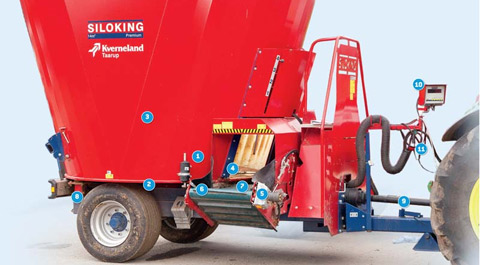
This may seem a strange place to start, but ensuring the oil level for the main gearbox and the two-speed transmission is at the correct level is essential. However, should this level indicator have been moved – by a wayward cow, for example – the level indicated may not be correct and, when servicing, Mr Crowe recommends checking the oil level at source – in the gearbox. The level indicator’s breather should also be checked to ensure it is not blocked.

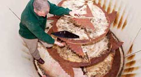
To check the oil level in the auger gearbox, it’s necessary to clamber into the hopper and remove a plate at the base of the auger which will then reveal the gearbox and the oil level screw. This is also a good opportunity to clear out the debris which accumulates behind this plate.

While you’re in the hopper, check the condition of the blades; those that are severely worn or damaged need to be replaced with new ones, which cost about £75 each.

The distance from the bottom of the auger and the floor needs to be as close as possible so that concentrates can be added early and mixed in with the other, more bulky ingredients. If the gap is too wide consider removing the metal lead strip and re-welding it at a lower level.

The drive to the main conveyor and elevator is hydraulic and, to dampen any sudden start up shocks, the drive has rubber inserts between the two aluminium drive components. Check to see that these inserts are intact and replace if required.

Conveyors are friction-driven from their rollers and need to be tensioned correctly. It should be possible to just lift the surface of the conveyor by about a centimetre. Adjustment is on either side of the front roller and, to ensure the conveyor is square on, the adjustments on each side need to be the same – measure to check.

This conveyor has a split in it which, left as it is, will only get worse. Time to glue it together and limit the damage for as long as possible.

For the weigh cells to weigh accurately they need to be firmly secured to the chassis – there are four bolts to check. Any movement of the weigh cell will result in inaccurate readings in the control box.

As with all powered implements, the pto guards must be in an undamaged condition – unlike this one which has been catching on a linkage arm and has a major split in it, as a result.

Control boxes are reported by Mr Crowe to be “bomb-proof”. He says a check on all the functions should be made to ensure all is well. If there is doubt about weighing accuracy, a pallet with, say, a bag of fertiliser can be placed on the hopper to provide a check.

With a generous amount of hydraulic hoses and electrical connections, it may be useful to know that Kverneland has marked each of the pipes with a colour-coded plastic tie both at the point where it enters the machine and at the hydraulic ram it supplies oil to. Electric controls for these hydraulic functions are also colour-coded to match those of the pipes they are linked to.

