Video: Guide to fitting a load-sensing trailer brake valve
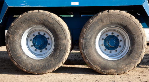
It’s all very well having razor-sharp trailer brakes when you’re fully loaded, but when you’re empty it inevitably means the wheels lock up and you’re left with clouds of smoke and prematurely bald tyres.
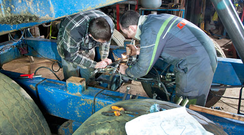
To get round the problem, Nick Fone gets some tips on fitting and setting up a hydraulic load-sensing valve from trailer braking specialist Mike Erentraut.
Watch the video and read the full report below.
When you’ve got ultra-sharp, tuned-up trailer brakes that will anchor-up no matter how heavy the load, there’s a high likelihood that they’ll do the same when empty.
That’s fine if you don’t mind getting through tyres at the same rate as Sebastian Loeb and you like to arrive at your destination with a bit of drama, accompanied by clouds of smoke.
However, not many of us can afford such showbiz-style entrances. And, thankfully there is a simple, relatively cheap way around the problem – fit an automatic load-sensing valve.
What is it?
As the name suggests, it’s a valve that will vary the supply of oil to the brakes depending on the load on the trailer.
When you’re fully freighted it’ll swing wide open allowing max oil flow through to the rams. Once you’ve tipped and you’re off down the road for the next load, it’ll shut right down, giving the brakes just enough oomph to bring the trailer to a stop without the wheels locking up. Aside from the obvious benefit of avoiding unnecessary rubber loss, it’ll also limit brake wear and hopefully help to reduce any risk of the trailer travelling sideways down the road.
How does it work?
A lever arm connected at some point between the chassis and running gear rises and falls with the body as it is loaded and emptied, opening or shutting the valve.
In most cases it is fitted to the main chassis cross-member between the wheels. A cable then runs down to a rubber-cushioned bar-linking front and rear axles and the lever-arm connects to this. (Linking up with both axles means that the effect of slopes and other lumps and bumps is evened out.)
Sometimes a rod is used in place of the cable but in the rough, tough topsy-turvy world of farming these don’t tend to last too long without being bent or broken.
Where a rocking-beam arrangement is used with stub axles or where there is no suspension, it’s pretty difficult to fit load-sensing. If that is the case but the machine in question has a sprung drawbar, it can be possible to fit the valve at the front end of the trailer (or tanker). Brake specialist Erentek advises against this while GES Hydraulics says its unit can be used for the purpose.
With either axle or drawbar sensing, as the load increases or decreases on the trailer, the valve senses the distance changing between the body and the axles (or hitch) and alters oil flow accordingly.
Is it tricky to fit?
In short, no. It’s getting it set up right that’s the fiddly bit.
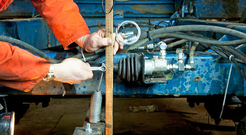
Positioning it is simple. It’s just a case of welding or bolting the valve-mounting bracket onto the chassis and then sticking a tab onto each axle to bolt the link bar to.
With the valve in situ, simple 1/2in inlet and 3/8in outlet couplings are plumbed in to the main brake line and adjustment is performed by changing the position of the cable clamp on the lever arm.
How much will it cost?
The Erentek version will set you back ¬£315 while GES Hydraulics’ unit costs ¬£347.60.
Most air-braking systems will have a load-sensing valve built-in but expect to pay a similar price of one of these pneumatic equivalents. (Setting them up is a different ball game altogether and really needs to be tackled by a specialist fitter).
1. LINK BAR
Make up a bar that will connect the two axles out of a piece of flat steel or angle iron. On most trailers this will need to have a crank in it to avoid it clashing with the main chassis cross-member. However, it doesn’t want to drop too low otherwise it’ll get ripped off on rutted tracks and mess with your ground clearance.
The bar needs to connect to the axles with rubber mountings at each end. Erentek supplies two pairs of rubber ‚Äòbobbins’ with bolts and brackets in each of its kits. Weld the brackets on to each axle as close to the centre as possible and then bolt the link bar to this.
2. VALVE UNIT
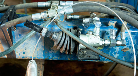
Positioned on the cross-member so that the centre of the lever arm is directly over the link bar, weld or bolt the valve assembly in place, making sure there’s ample room for the plumbing and access to the two test ports.
3. CABLE CONNECTION
The cable has a coil spring at one end, which should be bolted to the link bar directly below the valve block. It is then connected to the lever arm with a simple sliding cable clamp. Be careful to ensure the cable runs up the back of the lever and isn’t crimped by the threaded clamp bolt.
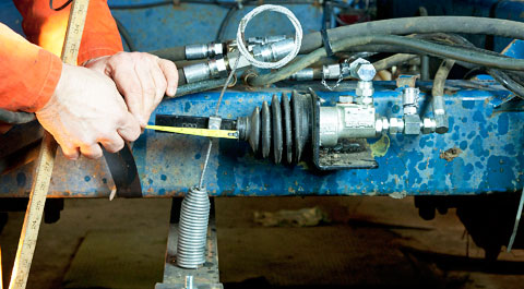
SET-UP STEP-BY-STEP
1. SUSPENSION TRAVEL
They key thing in getting the valve to do its job properly is to match lever-arm movement to the amount the body rises and falls when loaded and empty. (This can be anything between 15mm and 60mm, but generally will fall between 20mm to 35mm).
To do this, make a mark on the chassis and measure its height off level concrete when the trailer is unladen. Next, get it up to its normal loaded weight and re-measure. The difference is the exact amount of travel you’re aiming for with the lever arm.
2. CLAMP POSITION
Next job is to establish what point the cable clamp needs to be at along the lever arm.
As a guideline, if there is 20mm change in height between loaded and empty then the clamp needs to be about 40mm in from the pivot end of the lever.If suspension travel is closer to 60mm then it will need to be right out towards the end of the lever.
3. CABLE LENGTH
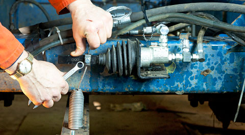
With the trailer empty, push the lever arm right down and tighten the clamp up on the cable in that position to set the minimum oil flow when the suspension is at maximum extension.
4. PRESSURE TEST
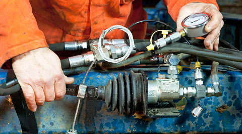
Beg, steal or borrow a hydraulic pressure gauge and, with a spare boot on the brake pedal, measure how much power there is at both inlet and outlet test ports with the valve lever both fully open and shut right down.
Most tractors should be pumping around 115bar down the brake lines but expect anything up to 150bar. (If it’s below 100bar, it’s probably worth getting a fitter to look at the tractor brake set-up).
So monitor what’s coming in to the valve and then what’s coming out when it’s wide open and the lever is in its uppermost position. They should be about the same.
Then measure the pressure coming out of the block when the arm is at its lowest and the valve is shut right down. It shouldn’t be anything lower than 25bar. A general starting point is about 45bar. Once you’ve road tested the trailer, re-adjust accordingly.
5. FINAL TWEAK
Using a meter ruler firmly planted on the deck, measure the total travel of the lever at the point where the clamp is bolted to the arm. This should match the difference in body position when empty to fully loaded. If it doesn’t, slide the clamp left or right along the lever to get the two to marry up.
More detailed set-up instructions can be had from Erentek – www.erentek.co.uk or 01522 720 065
ADJUSTMENT IN A NUTSHELL
Sliding the cable-clamp left and right along the valve lever arm adjusts for body/suspension travel loaded and empty.
Sliding the cable up and down through the clamp sets the minimum oil flow through the valve for braking when empty.
SIMPLER SET-UP
GES Hydraulics, based in Peterborough, is currently working on a cheaper, simpler load-sensing valve that is manually operated.
Effectively, a rotary restrictor valve plumbed in to the brake line at the tractor end, it requires the driver to switch from ‚Äòempty’ to ‚Äòladen’ positions when they’re loaded or have just tipped up.
Setting it anywhere in between then takes account of part loads.
It might sound like a simple solution but the company says it is still six months away from bringing it to market.