How to build your own tractor autosteer system for £700
 © Adam Clarke
 Anyone who has seen Clarkson’s Farm on Amazon Prime recently will have learned that driving in arrow-straight lines when carrying out fieldwork doesn’t come naturally to some.
It’s not only difficult, but it’s also tiring – operator fatigue after a long day concentrating on keeping each pass on the right track can be acute.
Most GPS-based autosteer systems come with a hefty price-tag and annual subscription that can add up to £20,000 – something that father-and-son team Alan and Peter Brookes couldn’t justify, particularly as their farm has a relatively small arable acreage.
See also: Farmers build ultra-accurate GPS system on a budget
However, Peter was determined to find a solution and, after shopping around for the right components online and getting them talking using open-source software, he’s managed to build himself a kit for just £700.
Flag markers
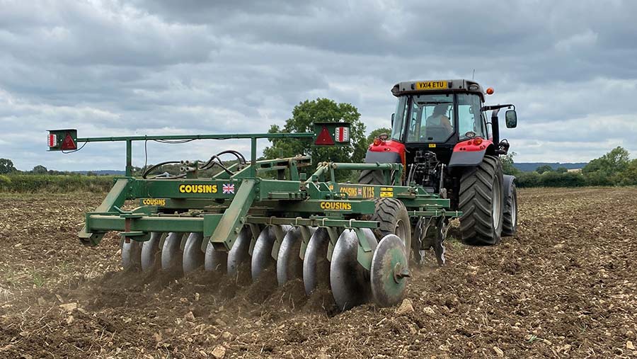
The business farms about 180ha at Wilmcote, near Stratford-upon-Avon, and is 75% grass and 25% arable, with the latter producing feed grain and straw for an 85-strong Charolais and Longhorn suckler herd.
At 23, Peter has started taking more responsibility – particularly with the tractor work – and says that when he started applying fertiliser in the spring, the farm was using flags to mark out each bout.
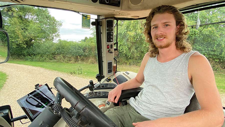
Peter Brookes © Adam Clarke
“I realised that I wasn’t great at keeping to the flags, so we moved to an Agricision Ontrak lightbar. It was OK, but staring at it was as tiring as using the flags.
“I envied those with autosteer, but thought it was a bit beyond our farm. Then I came across the idea of making our own in a Farmers Weekly article.”
Peter Brooks’ autosteer system – cost breakdown
- PCB – £5
- PCB components – £130
- Motor – £100
- GPS receivers – £430
- Miscellaneous – £35
*Note: laptop and 3D printer costs not included
Spring deadline
After some initial research, he found all the GPS jargon daunting, so the project was put on ice for a few months.
However, leading into last winter, he needed a hobby and set himself a deadline of spring 2021, which was the catalyst for knuckling down and completing the job.
The result is impressive, with the system costing very little money and now ensuring that all relevant fieldwork carried out with the farm’s main workhorse – a 115hp Massey Ferguson 5612 – is kept on track with +/-1cm RTK accuracy.
It was completed bit by bit, starting with the printed circuit board (PCB), as he considered this to be the most difficult part of the process. The PCB provides a way of connecting and facilitating data flow between all the other components.
Once he was confident this was functional, he then invested in the costliest essential parts left on the shopping list, such as the steering motor elements and GPS receivers.
He says the trickiest aspect of the whole process was learning and understanding all the terminology and how the different elements worked, as his experience with GPS systems was pretty limited.
“That’s where the AgOpenGPS forum was so useful. Most of the information I managed to find off my own back, but it gave me answers to the three questions I had, which kept me on track when I got stuck.”
Accurate application
With the spring deadline met, Peter says the biggest benefit has been on fertiliser application to the farm’s grassland, which is now far more accurate and efficient than before.
Cultivation work is a doddle, too. With jobs being completed faster and requiring less operator input, he is less fatigued and more inclined to catch up on other chores after a day in the tractor seat.
Peter believes any farmer should be capable of putting the system together, although older generations might find the software and computing more overwhelming than a traditional fabrication project.
“Like my first attempt, it may seem daunting at first, but it’s possible to learn all you need to know – you just have to be determined. Don’t be afraid to ask questions – I’m more than happy to help if I can.”
Below, Peter steers us through the process of making the system for those willing to have a go, with key resources outlined at the end.
Getting started
Building your own GPS – key resources
- AgOpenGPS Github
- PCB
- Arduino hardware/software
- GPS receiver
- RTK service
- Electrical components – Amazon and eBay
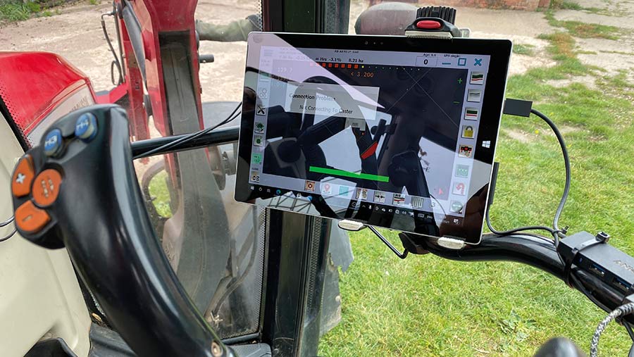
The first place to visit is the AgOpenGPS website, where users can download an open-source Windows software programme for precision agriculture features such as autosteer and section control.
The programme was first written by Canadian farmer Brian Tischler, who made it open source, which essentially means it is freely available for redistribution and modification by users.
Peter downloaded and ran the installer on his touchscreen Microsoft Surface Pro 3 computer and saved several support files required to run the autosteer function.
© Adam Clarke
This has now been updated to include headland turns and reverse steering, which required a minor modification to the autosteer control box in the form of a new inertial measurement unit (IMU) for £14.
On the same site, the AgOpenGPS forum can be found, where a significant number of threads can shed light on the process of producing your own GPS autosteer system.
Users are predominantly from North America, but there are plenty of Europeans with essential information about making it work in conditions closer to home.
Source a printed circuit board (PCB)
On the AgOpenGPS Github, users can find files containing several PCB designs and choosing the right one will have an impact on the ease of assembly.
Peter went for KaupoiMOD v3, as its design looked tidy and well thought out. However, when it came to soldering components to the board, its compact nature made it overcomplicated for a beginner.
For this reason, Peter suggests would-be autosteer makers go for a PCBA-Brian PCB, also available in the Github.
The chosen design file can then be sent to a PCB maker, who will make it and ship it back to the customer.
Peter went for Chinese company JLCPCB and it cost just £5. If in a rush, bear in mind shipping might take some time.
The PCB itself merely supports the electronic components needed to make all the parts of the GPS system talk to each other.
Most important is the brain of the system, known as the microcontroller. An example is an Arduino Nano, which allows users to download the code – or integrated development environment (IDE) – required to run the system on its flash memory.
Peter used an Arduino clone and experienced some issues when it was all powered up. A solution to this issue can be found among the forum threads.
Other components include connectors and terminals, capacitors, resistors, and diodes, which all need to be soldered onto the board in the correct place.
This process is fiddly but relatively straightforward, as everything is labelled and there are diagrams included in support files on the Github or Kaupoi’s OneDrive, along with the code that needs to be uploaded onto the Nano.
Acquire a GPS receiver with RTK correction
To get going, you can use just one GPS receiver and Peter opted for ArduSimple’s RTK starter kit, which includes an antenna and facilitates standard correction (+/- 10cm) with no repeatability.
To allow for more precise guidance, a second RTK starter kit was purchased to act as an RTK base station.
There might be base stations within your area that can be utilised, saving the need to buy your own, and these can be found online (see “Building your own GPS – key resources”).
This RTK starter kit included a wi-fi NTRIP programme preinstalled on the control board, which enables users to connect to an RTK service provider.
The antenna with the second kit was fixed to the chimney of his house, which for best accuracy should be mounted on a metal disc greater than 20cm in diameter and be within 20km of where the machines will be working.
A coaxial cable was then run down the wall and to a box in the house and the base station registered with RTK2Go.
Once connected to the domestic wi-fi, it relays the correction data to the AgOpenGPS programme in the tractor via a wi-fi hotspot created on the operator’s mobile phone.
As this only transmits small amounts of data over the course of a day, 4G or 5G speeds are not necessary, so even in areas with poor mobile signal, the system should still work reliably.
Build the steering unit
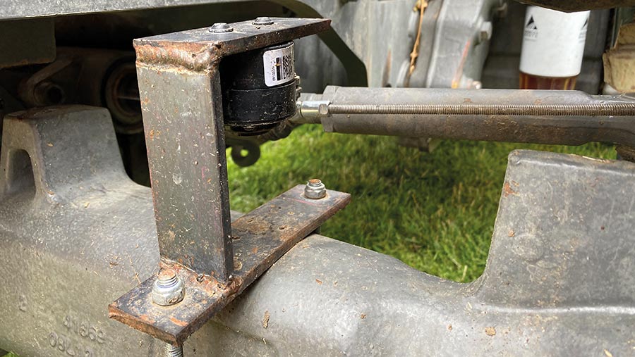
For the autosteer to function, the system needs to know the angle of the front wheels via a sensor.
Peter opted for a Delphi ER10031 suspension self-levelling sensor mounted on top of the axle on a mild steel bracket.
© Adam Clarke
This was connected to the axle kingpin by a small gas strut and threaded bar bought from eBay, and a cable runs up to the cab where it connects to the box containing the PCB.
The final part of the system was the steering unit and switch.
It is possible to use the tractor’s hydraulics if it is autosteer ready, or retrofit the right hydraulic valves to enable its system to do so, but Peter opted to make his own motorised unit.
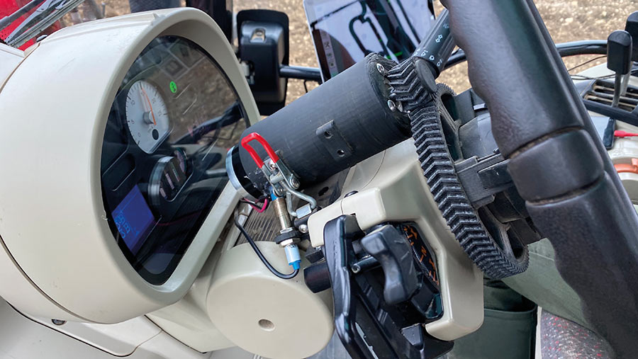
© Adam Clarke
Using his computer aided design (CAD) and 3D printing experience from A-level product design, he devised most of the drive components himself around the 24V electric gear motor that turns the wheel.
Having his own 3D printer – which can be bought for about £200 – allowed him to produce the cogs and other components in-house, as sending designs away for printing can soon rack up additional cost.
This is particularly the case when prototyping, where a few attempts may be required to make everything fit.
While it’s possible to machine harder-wearing parts such as sprockets out of steel, this is again expensive, and 3D printing allows him to make cost-effective replacement parts from plastic as and when they are needed.
A Heschen M12 proximity sensor steer switch – which engages and disengages the autosteer – was purchased from Amazon and simply wired into the control box via a nine-pin serial port, with its location clearly labelled on the PCB.
To power the motor, a Cytron MD13S and step-up convertor was used. This converts the 12V supply from the tractor to 24V and is connected to the autosteer box using a two-pin aviation connector.
The unit is clamped to the 5612’s steering column. This was a tricky process without hacking away at its plastic cover, but it’s now sturdy enough to support the system when in work.